I'm working on an idea for my own BMS (battery management system), here is some details on my initial research:
last night I started prototyping with this device I purchased ($20)
http://www.rfduino.com/product/rfd22102-rfduino-dip/
I originally purchased an adafruit BLE shield to use with a Arduino
Micro/Trinket but I broke it during assembly/testing. So the RFduino
will be the first proto child.
Step 1 initial software setup: I got the RFduino loaded up with a
template "sketch" software and broadcasting from a standalone battery.
the template looks similar to this: https://github.com/RFduino/RFduino/b...e/Template.ino
Step2: communication: Got the free tester Android app installed and was
able to send and receive data to my phone. link to Andriod tester: https://github.com/lann/RFDuinoTest/releases
added code to Arduino sketch code template:
void RFduinoBLE_onReceive(char *data, int len)
{
// anytime we receive a char from Andriod we send back the only useful data we have at the moment
//read pins 5 and 6 and report integer from 0 to 1023
int vlt;
vlt = analogRead(6);
RFduinoBLE.send(vlt);
vlt = analogRead(5);
RFduinoBLE.send(vlt);
}
step3: measure something real and report.
I learned the microcontroler cannot measure it's own supply voltage
without help. Either use a voltage divider or an external reference.
The divider formula is?
Vout = Vin * (R2 / (R2 + R1)) *edit* due to voltage sag this could be
too innacurate except in comparing relative readings across all cells.
For any decisions on shunting/balancing, we would need to multiply and
regulate the supply? so measurements can be useful.
step4: see if the measurement can be added to the bluetooth broadcasted
device name so there is no connection needed and the andriod device can
simply scan all device names, then pick one to connect to when desired.
eg.
RFduinoBLE.advertisementData = "vCell1"; //but real voltage in there somewhere
Tuesday, December 9, 2014
Friday, November 21, 2014
round trip to work
I drove the 32 miles round trip to work without any charging along the way.
Last night my daughter had to rescue me by following me home in the dark with her Camry since my car reportedly had "no taillights" which turned out to really be "dim taillights". So I need to put new clean connectors on along with the LED taillights I recently purchased but have not yet installed. This weekend!
josh
Tuesday, October 14, 2014
Rear battery boxes
I completely scrapped the location of batteries in the rear passenger
seating area. This poses two problems, first batteries favorite
position is not laying sideways but standing upright. Second the
limited space made me forget about padding and the batteries were fixes
very tightly. I've since learned that someday somewhere in some car, a
battery will bloat, and if there is no side to side room whatsoever,
cracking may ensue. Finally having 4 cable runs to facilitate 4
locations for blocks of batteries is hard to deal with from a BMS
standpoint, and also could cause minor issues with charging. In short
complication rarely pays off. So keeping 26 cells in the front for now,
everything else will go in back.
Just starting new rear boxes:

Bending metal with break thingy...
Rubber mounting, I got some flat rubber , kinda looks like tire rubber but has thread instead of steel inside it.

Unexpected Feline Supervisor:

comparision of welded boxes to bend metal with no sides yet:


I cut a massive hole in the rear trunk area sheet metal of my Cortina, where the old gas tank hole was. The new much larger hole runs in-between the leaf springs and just behind the rear differential.
Cut, bent and welded a bunch of 16 gauge steel sheet (wore a respirator for the galvanized pieces). Thus creating 5 horizontal boxes which hang down 5 inches from the original trunk floor. The boxes hold horizontal parallel rows of batteries, which finally appear like one square pack, except for a small gap for the final row making room for the leaf spring shackles.
The leaf does not pass under the boxes, the edges of both are 1 inch apart.
I also removed the leaf springs and delivered them to Denver Spring company to have one leaf added. I had previously lengthened my spring shackles which made my car driveable but the leafs were flat, not good.
I have not painted the boxes, some are galvinized which helps but some are raw steel and need primer. Plus all the cracks etc need foam padding and/or some method of sealant.
Then finally a magic wand is needed to create "the perfect lid", for starters that will end up being some plywood lined with foam from the battery shipping boxes.
Just starting new rear boxes:
Bending metal with break thingy...
Rubber mounting, I got some flat rubber , kinda looks like tire rubber but has thread instead of steel inside it.
Unexpected Feline Supervisor:
comparision of welded boxes to bend metal with no sides yet:
I cut a massive hole in the rear trunk area sheet metal of my Cortina, where the old gas tank hole was. The new much larger hole runs in-between the leaf springs and just behind the rear differential.
Cut, bent and welded a bunch of 16 gauge steel sheet (wore a respirator for the galvanized pieces). Thus creating 5 horizontal boxes which hang down 5 inches from the original trunk floor. The boxes hold horizontal parallel rows of batteries, which finally appear like one square pack, except for a small gap for the final row making room for the leaf spring shackles.
The leaf does not pass under the boxes, the edges of both are 1 inch apart.
I also removed the leaf springs and delivered them to Denver Spring company to have one leaf added. I had previously lengthened my spring shackles which made my car driveable but the leafs were flat, not good.
I have not painted the boxes, some are galvinized which helps but some are raw steel and need primer. Plus all the cracks etc need foam padding and/or some method of sealant.
Then finally a magic wand is needed to create "the perfect lid", for starters that will end up being some plywood lined with foam from the battery shipping boxes.
Thursday, September 11, 2014
It's been a while since the last post, but there has been LOTS of work done. Mainly with updated motor mounts, and purchasing an industrial strength motor adapter and coupling. Also finally getting the flywheel sorted out and balanced. Building my own engine hoist, organizing my garage! (an ever ongoing cause). Got temp registration, etc. Pictures coming!
Sunday, August 17, 2014
Has been a busy few days!
Has been a busy few days!
Mounted accelerator cable / pot.
Built the front side battery box seen here, in 16 gauge steel.
Mounted the Soliton Controller at a double angle facing sortof up and toward the front of the car. And finally hooked up the motor HV wires and one battery cable coming from the rear pack.
I'm not putting anything else of size in front of this stuff because I want air flow, so maybe just a tunnel system of some kind if I ever think of what, any ideas?
The battery box will have a deep lid.
Thursday, August 7, 2014
sold the V8
The other day I managed to sell the V8 302 for $700. Was cheap but I'm happy with that considering I really can't give the buyer any good info on how reliable the motor will be.
I have been working on the motor mounts and plate for my electric motor and it is installed into the car. There is a gap there between the motor plate and the transmission bell housing, the gap is firm with some large bronze spacers, but really that is still a temporary solution (but strong enough that it could be permenent)
Regardless I will have to disassemble the setup to put in an aluminum flywheel or at least get the steel flywheel that is in there now balanced (Ford has a stock purposely imbalanced setup to compensate for internal motor imbalances)
-josh
Saturday, July 12, 2014
Changing over to FORD !
I recently bought a 1965 Ford Cortina (Lotus-Cortina) which is now in my garage and will be my new chassis for me EV conversion.
After 6 or 700 miles on the Volkswagen I decided to move to a more substantial chassis that can handle more batteries for longer range and be my only car! The VW has been good to me and convertibles have their addictiveness, but it is now gone, sold the chassis for 400 less than I paid for the car a year ago (also sold the motor when I first got it)
Anyway on to Ford, but wait... is it a Ford? Well yes made in England as almost all Mk1 Cortina's were, but it has our normal left hand driver side. pics please? well here is something...
This car has a 80's Mustang GT rear end (shortened) with T-5 transmission and V8 302 roller motor. Only the motor will need to be tossed out, it is super powerful but wasn't really well taken care of so I may just part it out so someone doesn't end up with an unknown situation.
So today I am removing the old gas tank which is a plastic racing style tank (this car was probably on the track at some point in the last 15 years) AND hopefully I can remove the V8 with my engine hoist. Since there was no A/C no P/S no Fuel Injection no Computer system of any kind, and no heater system, we are looking at a countable number of bolts to get this thing removed, I am hopeful!
Josh
After 6 or 700 miles on the Volkswagen I decided to move to a more substantial chassis that can handle more batteries for longer range and be my only car! The VW has been good to me and convertibles have their addictiveness, but it is now gone, sold the chassis for 400 less than I paid for the car a year ago (also sold the motor when I first got it)
Anyway on to Ford, but wait... is it a Ford? Well yes made in England as almost all Mk1 Cortina's were, but it has our normal left hand driver side. pics please? well here is something...
 |
| parked in my garage, 13" wheels, ya know, british style. |
 |
| V8 small block 302 roller motor that has to come OUT and be sold off |
 |
| shiny from the showroom of the dealership in Chicago (whom I don't like much) but anyway, it WAS clean then. they used bad shipping with no cover and now it is dirty :( |
This car has a 80's Mustang GT rear end (shortened) with T-5 transmission and V8 302 roller motor. Only the motor will need to be tossed out, it is super powerful but wasn't really well taken care of so I may just part it out so someone doesn't end up with an unknown situation.
So today I am removing the old gas tank which is a plastic racing style tank (this car was probably on the track at some point in the last 15 years) AND hopefully I can remove the V8 with my engine hoist. Since there was no A/C no P/S no Fuel Injection no Computer system of any kind, and no heater system, we are looking at a countable number of bolts to get this thing removed, I am hopeful!
Josh
Thursday, May 8, 2014
time lapse
In the last 3 weeks I went from: batteries in the trunk...

to chopping up my car

to Mocking up an idea that seemed fairly easy

to these finised metal boxes, which wasn't easy...

lots of new skills learned, people and places met, and a few scratches. no burns or ruined eyes or ears!
to chopping up my car
to Mocking up an idea that seemed fairly easy
to these finised metal boxes, which wasn't easy...
lots of new skills learned, people and places met, and a few scratches. no burns or ruined eyes or ears!
Friday, April 18, 2014
welding battery boxes
I tried a wood/metal-brakets version which was okay, but the wood thickness used up valuable space plus it would have to be bolted to the brakets and bolts use up more space poking themselves into the box area. SO I decided to try the metal approach.


Here is some physical progress on my 3 week brainstorm of a new battery location.
After
finding possibly the best supplier of sheet metal a guy could hope for,
I used my brand new MIG welder to tack weld up this box out of 16 gauge
sheet steel, which looks shiny like stainless but it is not stainless
and will need to be painted. (Powder coating would be nice, but I think
I'll just go with paint for now).
I'll try to get the 2nd box, which holds 1 row of horizontal batteries done tomorrow.
And yes, the auto darkening welding mask is worth 10 times what they cost!
some early christmas presents
these arrived a few weeks ago as well. various ideas leads to feeding my shopping addictions:
I received my Vicor Maxi DC / DC today, and wow is it tiny!
Not really sure how the "evaluation board" is going to fit into the picture, but I'm kind of glad I bought it...
Also my Raspberry Pi which is now running the Orion BMS software via USB to the unit, but I will be programing my own lite version to show minimal diagnostic data. The 7" display is not touch, and I finally realized I didn't want that thing in my car along with some sort of mouse/keyboard contrpation. Besides at $150 it was too expensive to have laying around a convertible VW. At $35 the Raspberry Pi is a reasonable loss.

So anyway, this Vicor, and evaluation board (which might get relabeled to "production board" by me), I don't really know how to start with it, I suppose I'll just hook it up to my traction pack and see if it blows up.

and the front side faced down into the board:

*shrug* anyone got a suggestion on what to solder first?
it's so tiny! reminds me of a deck of cards, so maybe I should head to Blackhawk and play some NLHE tomorrow? Live Casino Poker really is a lot closer to a slot machine than you'd think.
I received my Vicor Maxi DC / DC today, and wow is it tiny!
Not really sure how the "evaluation board" is going to fit into the picture, but I'm kind of glad I bought it...
Also my Raspberry Pi which is now running the Orion BMS software via USB to the unit, but I will be programing my own lite version to show minimal diagnostic data. The 7" display is not touch, and I finally realized I didn't want that thing in my car along with some sort of mouse/keyboard contrpation. Besides at $150 it was too expensive to have laying around a convertible VW. At $35 the Raspberry Pi is a reasonable loss.
So anyway, this Vicor, and evaluation board (which might get relabeled to "production board" by me), I don't really know how to start with it, I suppose I'll just hook it up to my traction pack and see if it blows up.
and the front side faced down into the board:
*shrug* anyone got a suggestion on what to solder first?
it's so tiny! reminds me of a deck of cards, so maybe I should head to Blackhawk and play some NLHE tomorrow? Live Casino Poker really is a lot closer to a slot machine than you'd think.
brainstorming the battery move
few weeks ago...
After scary fun with a reciprocating saw, and nearly destroying my car?
Last night I did a pegboard mock of my sub-level battery holder. Here is some pics.
first the scary hole (opps did I just ruin my EV?)
The large angle iron seen is the rear axle, has no vertical or lateral movement but it does swivel slightly so nothing can be touching it.

more cutting, and then the pegboard mock...

overhead shot, make sense? Total of 3 rows of 15 batteries = 45 = 144v
just the thought of moving this weight lower and in front of the rear axle makes me happy from the viewpoints of suspension/handling/catastrophe

is it okay to have 1 row of batteries laying on their sides? I'm pretty sure I read that it is okay but still not certain.
After scary fun with a reciprocating saw, and nearly destroying my car?
Last night I did a pegboard mock of my sub-level battery holder. Here is some pics.
first the scary hole (opps did I just ruin my EV?)
The large angle iron seen is the rear axle, has no vertical or lateral movement but it does swivel slightly so nothing can be touching it.
more cutting, and then the pegboard mock...
overhead shot, make sense? Total of 3 rows of 15 batteries = 45 = 144v
just the thought of moving this weight lower and in front of the rear axle makes me happy from the viewpoints of suspension/handling/catastrophe
is it okay to have 1 row of batteries laying on their sides? I'm pretty sure I read that it is okay but still not certain.
Sunday, March 30, 2014
gas tank removed
I've driven the car to work a few times, realized I need a dc-dc converter otherwise I somehow managed to push my car along the street twice because I let my 12v die.
But the new news is the gas tank is out!, which was a pain because the rear axle must be lowered. But the non-pain part is it is possible to do this all without disconnecting any brake lines, whew that would be messy.
But the new news is the gas tank is out!, which was a pain because the rear axle must be lowered. But the non-pain part is it is possible to do this all without disconnecting any brake lines, whew that would be messy.
 |
| the dirty wall straight ahead is a vertical space where the rear passengers calves dangle down, so all the space behind that up to the thick metal in the foreground, is maybe 5 cu feet of space well protected and a nice candidate for batterys. |
 |
| under side open space. you can see the lumps where the rear passengers but used to sit. |
 |
| if i cut something like the yellow outline, maybe I can end up with a large cavity of space to install a battery box. This has lots of appeal. Perhaps it will reveal better handling due to the big weights being between the axles instead of behind the rear. also lower center of gravity *shrug* |
 |
| yellow line for possible cutting |
 |
| all gone! |
 |
| THE gas tank |
Wednesday, March 5, 2014
Licnese Plates!
I received my Colorado license plates today, along with a new little EV
sticker they started in 2014 that is placed in the front window in order
to park in spots where chargers exist (without getting a ticket).
I also purchased a Raspberry Pi with a 7" screen to install into my EV so it can show live data from the SolitonJr and the Orion BMS on the dash (as well as watch movies and listen to music?), yet another project latching onto me!
I also purchased a Raspberry Pi with a 7" screen to install into my EV so it can show live data from the SolitonJr and the Orion BMS on the dash (as well as watch movies and listen to music?), yet another project latching onto me!
test drives
Last week we did two 15 mile test drives.
This week I drove 27 miles round trip (without knowing if I'd make it home because I still don't have my e-meter setup) to my appointment with the Colorado Motor Vehicle Emissions Technical center, and they signed off a form DR2365 I needed to get my E type registration/title! I was pretty nervous, and some things went wrong before I arrived. 6 blocks away my car lost power due to my old rickety 12v battery dying off (still no dc/dc converter). So in the parking lot next to the one I 'rolled' into, there was a meineke auto shop which happily stocked and sold me a new charged battery ($120 later) and I installed it there in the beautiful Colorado winter sun, and arrived at my appointment three min early. (with the convertible top down!)
Things that went right?
1) I didn't get pulled over for my 3 month expired temp tag.
2) They signed the form needed.
3) I made it home without running out of electricity in my traction pack!
4) my new battery didn't die.
whew.
did get some video, will post soon.
Saturday, February 15, 2014
major issue
Added another motor mount. Let see if vibrations feel better now.
Somewhat major setback occured today when I went for another test drive (with 2 added motor mounts) to see how things felt and listen/watch for vibrations etc. As I was coming home I lost power to the drive train but the motor was still spinning up (but did not over-rev). And was definitely not spinning the trans in neutral either, just zero drag.
I looked through the open hole where the old starter motor used to mount on the trans, and could see that the coupler/clutchplate system was not spinning either, so I guess that means the splines are not stripped. My guess is the coupler slid down the shaft and off of the motor? I was not under heavy power, in fact I may have been coasting somewhat (as I crested a small hill).
I suppose the good news is, nothing sounded like it was breaking or tearing, there was no loud sounds, just lost power while going slow. still a bummer, as I will have to remove the motor at the very least. Possibly also the trans (hopefully not).
Other minor good news, the switches I put in the dash to power up the controller and the contactor are working, plus my rear lights are working. And it was nice I didn't have to tow it back, I was able to roll far (because I took the time to pump up the tires extra firm) small victories.
Other minor bad news I could not get her in reverse, my shifter linkage must not be quite right.
josh
Friday, January 31, 2014
Better Motor Mounts
Motor mount improvements. My two goals were to 1. use ALL the existing/previous mounts in the compartment 2. have at least one mount connect to the large 1/2" bolt called "lift-eye" bolt in the center of the motor which is extremely strong. The other mount on the back of the motor has two holes and is strong also, but it is two aluminum 5/16" screw holes, probably about the same as one 1/2" steel mount. Plus the two spots are entirely separate functional parts of the motor, so I guess technically if the motor fell apart within itself both major pieces would remain connected to the frame? Seems like a remote bonus, hah.
Total of 4 mounts are in use now, two for motor and two for transmission. Since the motor and transmission are very secure together as one unit due to the plate and 5 bolts, the entire assembly has 4 mounts.
Total of 4 mounts are in use now, two for motor and two for transmission. Since the motor and transmission are very secure together as one unit due to the plate and 5 bolts, the entire assembly has 4 mounts.
 |
| Front motor mount, seems flimsy by itself but it provides front to back strength, an area which the other new mount is weakest in. Has some rubber on the motor connecting bolt (eye-lift bolt) |
 |
| This new motor mount is the strongest one and provides very strong side to side and up/down strength, has a small amount of rubber in there somewhere. |
 |
| Bottom show of strongest mount. |
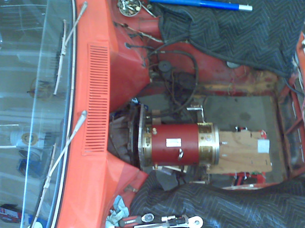
 |
| This is an old shot of the wiring getting finished up from the controller to motor, the wood block is just to keep them from flopping around. |
Wednesday, January 15, 2014
HV wires
A few days ago Jori and I added to the rear compartment wood setup to
get things nice and sturdy with tie-downs. It isn't final but will be
good for test drives, etc. Very importantly we reassembled the brake system which I inadvertantly took apart, this was a pending item of doom and now is back to normal. I'm hoping I can do a test drive without the electric vacuum assist pump installed, but we shall see. If I go down my drive way and have nothing but E brake then I'll have to put her in reverse!
And I did another long cut on the aluminum plate adapter up front. Even though it's fully installed I was able to use the reciprocating saw to shave off another slice to make it fit better in there. That cut is a pain but I'm getting better at it, and thinner shorter metal blades help too.
(last night I sewed some boxers using some light blue 50/50 cotton/linen fabric that I ordered up a few months ago, I really was too lazy to do laundry, so instead I spent 3 hours at the sewing machine? but they fell good! Jori got pics of me standing at the sewing machine with only a tee shirt on)
 |
| Not all batteries are in at this point, just getting them in there roughly |
 |
| running the HV wires up the side, same route as the large pack of wires that normally go from the dash to the rear lights |
 |
| Heavy frame bar that provides a nice safety brace for the batteries (which will eventually be in a strong closed box) |
And I did another long cut on the aluminum plate adapter up front. Even though it's fully installed I was able to use the reciprocating saw to shave off another slice to make it fit better in there. That cut is a pain but I'm getting better at it, and thinner shorter metal blades help too.
Today! was good (and still is) Firstly
I drained the gas, still had 2 gallons so that was a smelly process. I
removed the filler system/inlet and all the wiring and sensors for the gas
tank measurements, etc. I loosened the tank itself but didn't get it
all the way out, there must be some tricks to getting it out, mainly I
just needed it empty so it doesn't pose a hazard and I cut all the
cables and metal hoses out of the car having to do with fuel altogether.
 |
| Secondly I ran the big 2/0 gauge HV wires (welding cable) from the back to front, through the firewall which is tricky without removing the dash, but I think I have it worked out. |
This cold season and the New Years trip to Vegas by car (gas powered Camry) slowed progress down some, but we are back at it.
A few weeks back I finally got things straightened out with my Elcon charger, the Orion BMS, the serial CANBUS interface between the two, and the bank of batteries. Everything setup on my kitchen table with 50+ wires going all over the place, I got a full charge on my batteries with a real time visual on each battery as they balanced, etc. A full charge is nice so I can do a test drive without yet installing the BMS or Charger into the car.
While my parents were in town over Christmas my Mom helped me build up the trunk area with wood for supporting the batteries. It's nice there is a very thick and tall heavy duty steel support directly behind the rear seats that provides a nice safe way to keep batteries separate from people in the case of an auto accident. We also brewed up 5 gallons of stout which is now in the bottling stage. yummy! (pictures coming)
Subscribe to:
Posts (Atom)